For this project, I’m going to show you how I installed a modchip in my PlayStation using a cheap Arduino development board. This modchip allows the PlayStation to read burned game backup disks and play games from other regions. As a bonus, this modchip was a piece of cake to install!
These days, there are so many ways to play PlayStation 1 games. You can play your PS1 favorites on a PS3 or a PS2. You could pick up one of the PlayStation classic systems or try out an awesome emulator like Duckstation. There are even ways to play PS1 titles on Sony’s handheld devices, the PSP and the Vita. But the original gray box PlayStation has a special place in my heart. The original Sony PlayStation is one of my absolute favorite game systems due to its diverse library of games and my nostalgic connection to the console. This weekend, after an absolute bummer week of work, I was setting up my CRT, getting ready to relax and play some video games. At some point it occurred to me that I needed a way to play my PS1 backups on the original console. Most modchips for the PlayStation will allow you to run burned discs, games from outside the console’s region and homebrew, even though there is not much homebrew out there for the PS1. While looking for a way to modify my PlayStation I discovered an amazing project called PsNee.
PsNee is an open source stealth modchip that works on every version of the PlayStation 1. PsNee is designed to run on Arduino boards, which is super convenient. If you have seen any of my YouTube videos, you probably know that I keep several Arduinos in stock. The supported varieties include the Arduino Uno, Leonardo, Nano, Mini, The Pro Micro (3.3v), and the Pro Mini. For my modchip, I will be using the Arduino Nano. ATtiny25, 45 and 85 chips are also supported but you will need a special programmer to write the PsNee code to these chips. The PsNee code is available on the Kalymos Github page. I found the documentation of PsNee installs to be really good. The PDF installation guide contains links to William Quade’s website for more detailed information about each version of the PlayStation motherboard.
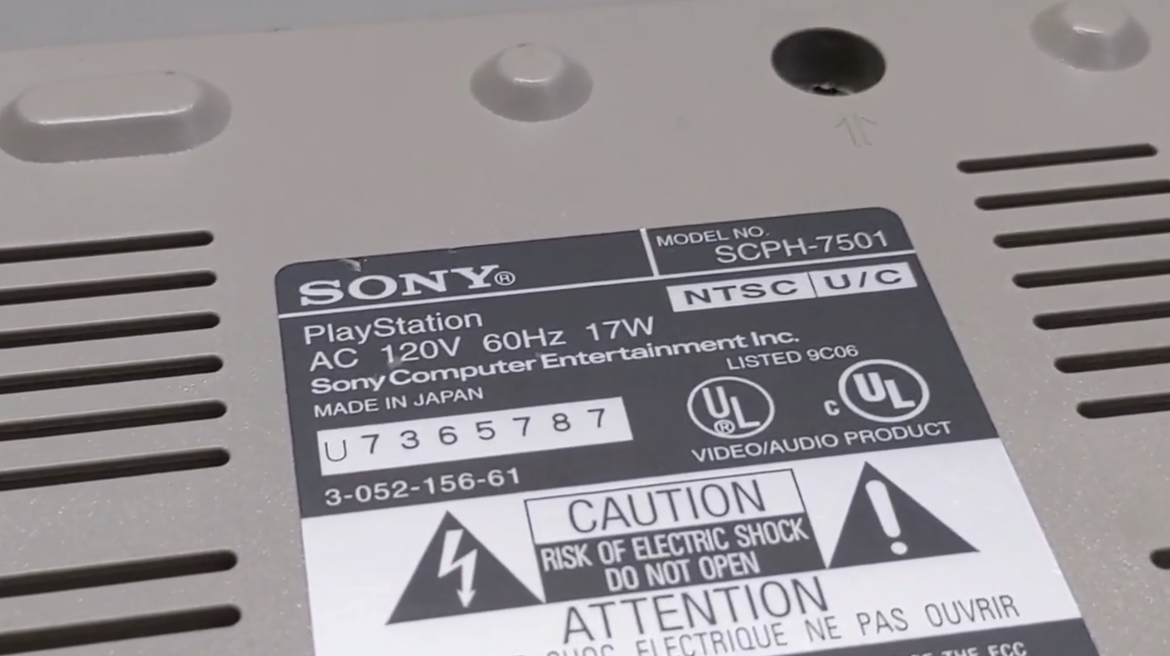
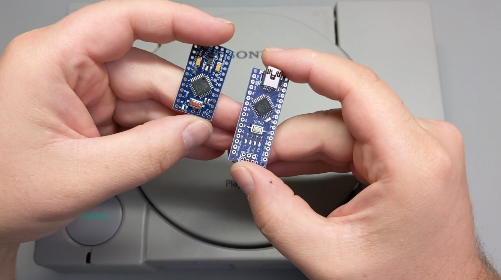

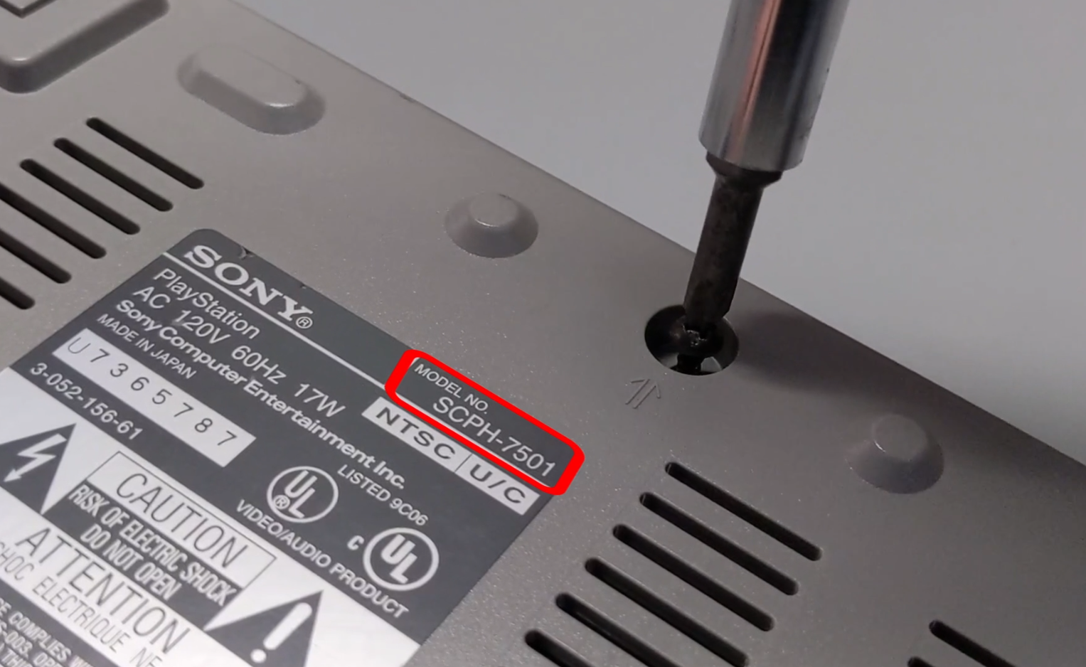
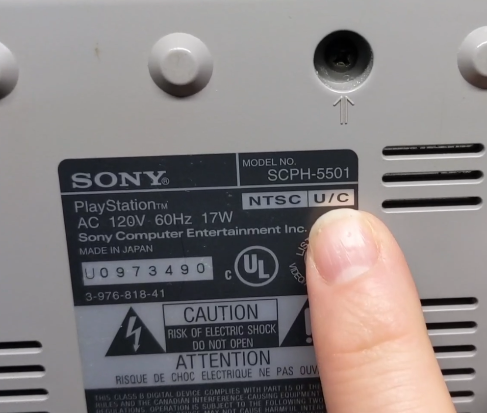
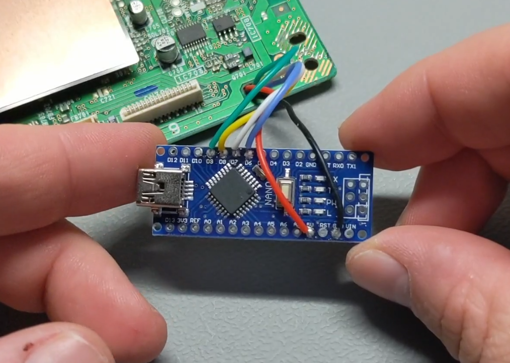
So, If you want to install one of these you will obviously need a PlayStation. It doesn’t really matter what model since there are wiring diagrams for each revision. In this example I will be using a SCPH-7501 and I will also show you my SCPH-5501 PlayStation just to give you an idea of what different versions might look like. You will need to pick up an Arduino. Any of the supported boards are fine but I would recommend the Nano because it is cheap, easy to find and you can program it with a normal mini USB cable. The pro mini is also a great choice because it is small and flat. This makes it easier to hide inside the console but to program it you will need an adapter.
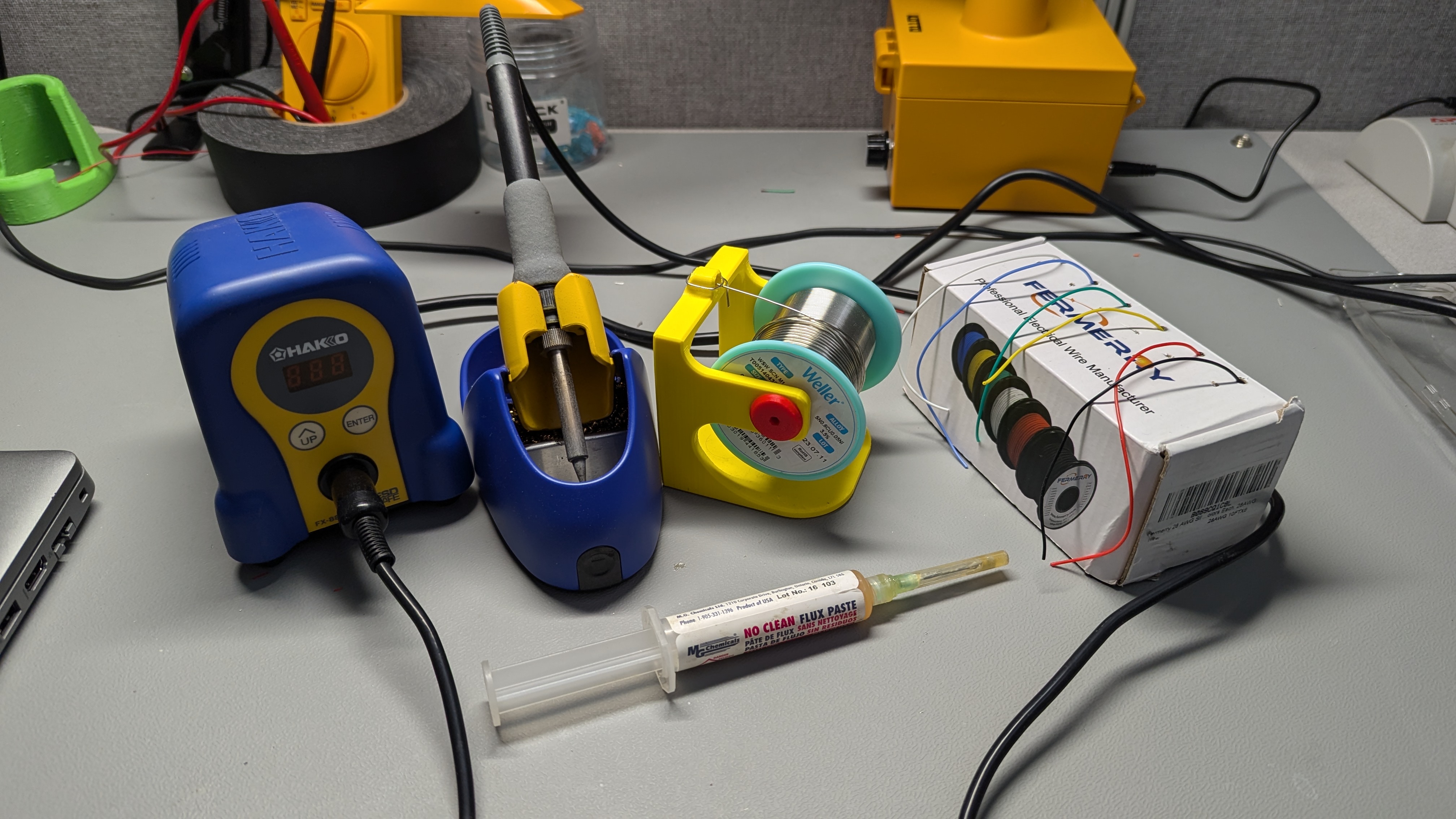
To install the chip you will need a soldering iron, some solder, flux, and wire. I’ll be using 28 gauge wire. This is completely optional, but depending on your install, you may want some Kapton tape to insulate the modchip or soldering points.
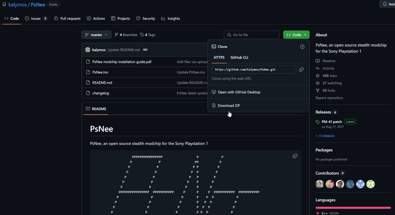
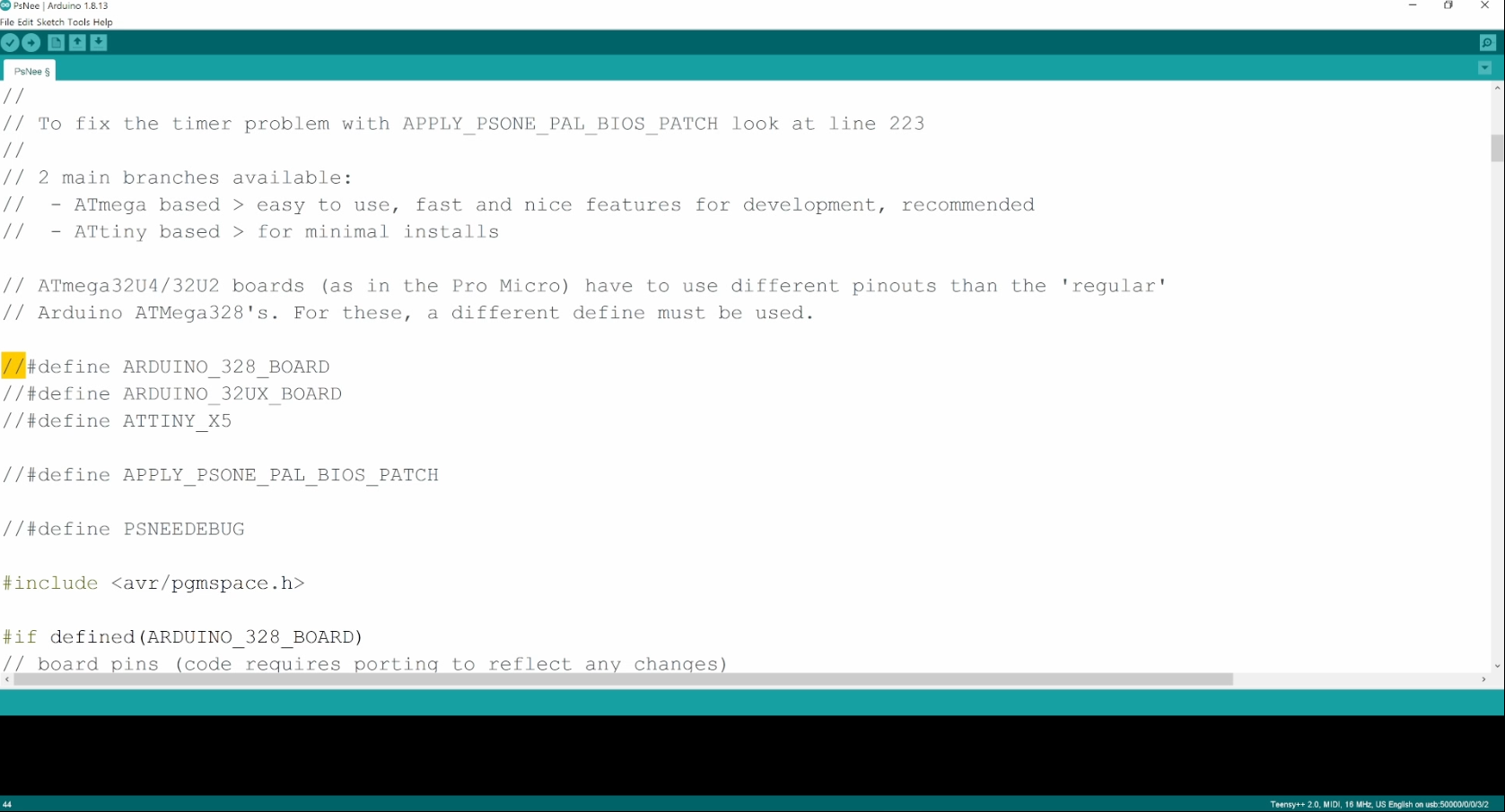

First, navigate to the PsNee GitHub page and download the Arduino INO file. Open this file in the Arduino IDE. The Arduino sketch contains instructions on how to set up the code for the board of your choice. All you need to do is uncomment the line for the microcontroller you will be using. I will be using the Arduino Nano, so I need to delete the slash marks on the line that says “#define ARDUINO_328_BOARD”. That is the only change that needs to be made so now we can go to the tools menu. Here, you must select the Arduino board you are using and the port it is connected to. You can determine the port by plugging in the Arduino and seeing which port appears. The COM ports can also be verified by opening up device manager. Next, click upload and wait for the done uploading message. Now the PsNee modchip is ready to install.
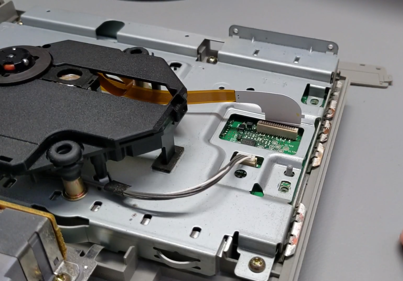

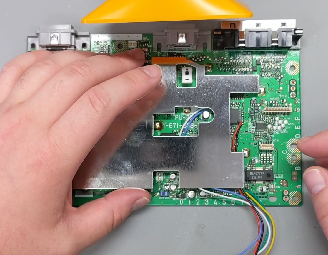
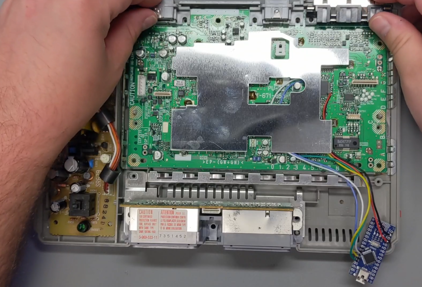
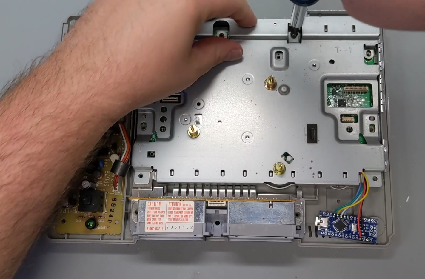
I’m going to disassemble this SCPH-7501 PlayStation down to the motherboard so we can get this modchip installed. Thankfully, this system is not too hard to take apart. Just 6 screws on the bottom then 2 cables to unplug to remove the optical drive. Then the power supply connection and the controller port cable must be removed. 4 screws hold the internal metal frame together and underneath that, there are 4 screws holding the motherboard in at the back of the system where the I/O ports are.


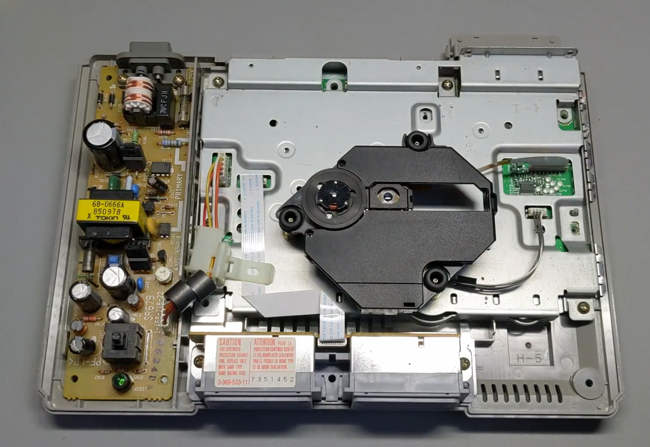
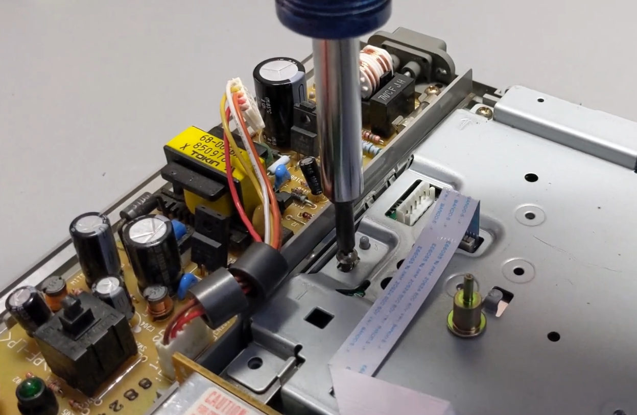
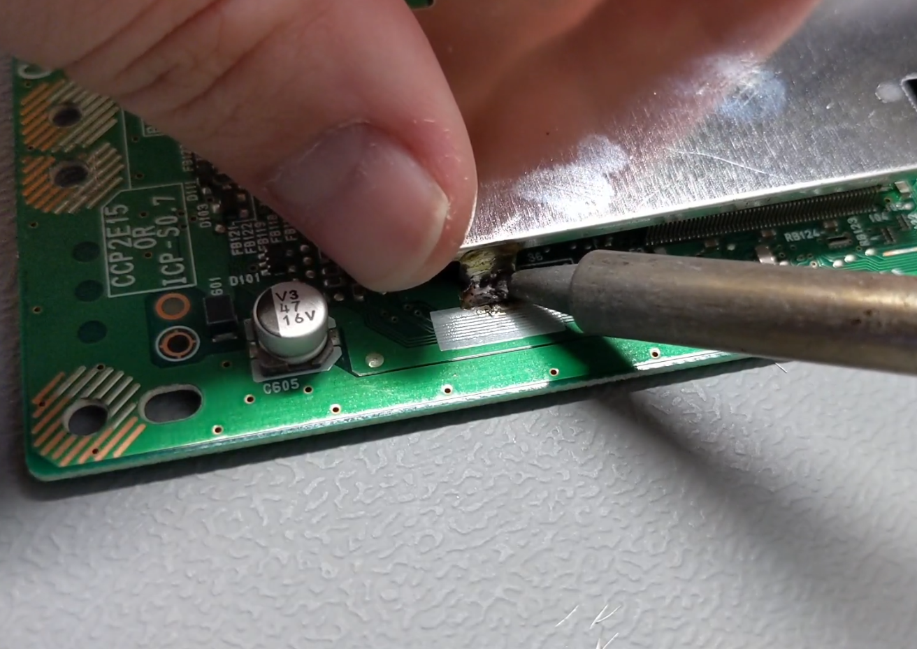
This version of the PlayStation has this metal shield on top of the motherboard. Not all versions have this piece. This piece needs to be removed to access the connection points for the modchip. To remove the metal shield, grab the soldering iron and heat up the points where the legs of the shield contact the PCB. The shield is flexible enough for you to lift these connections one at a time and let the disconnected solder point cool down. After disconnecting all of the solder points the shield will lift off easily.
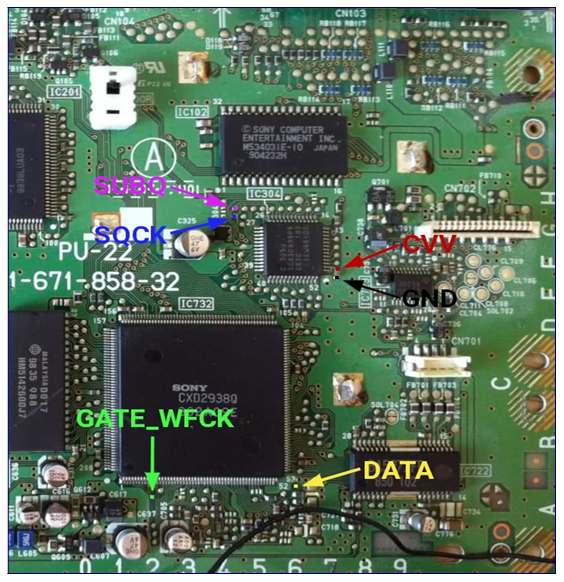
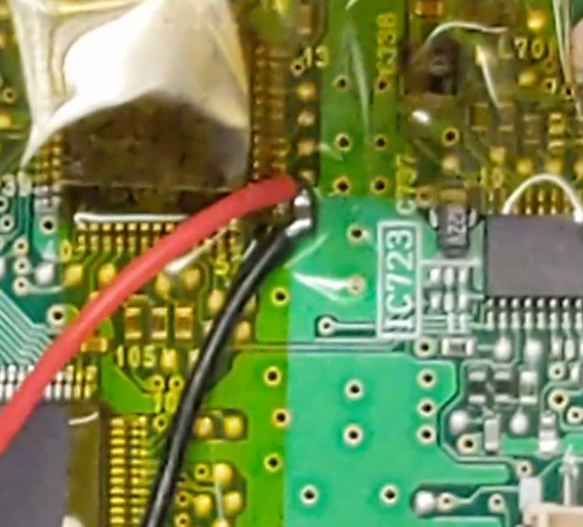
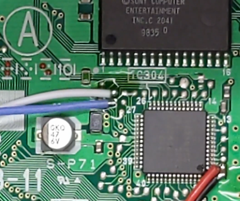
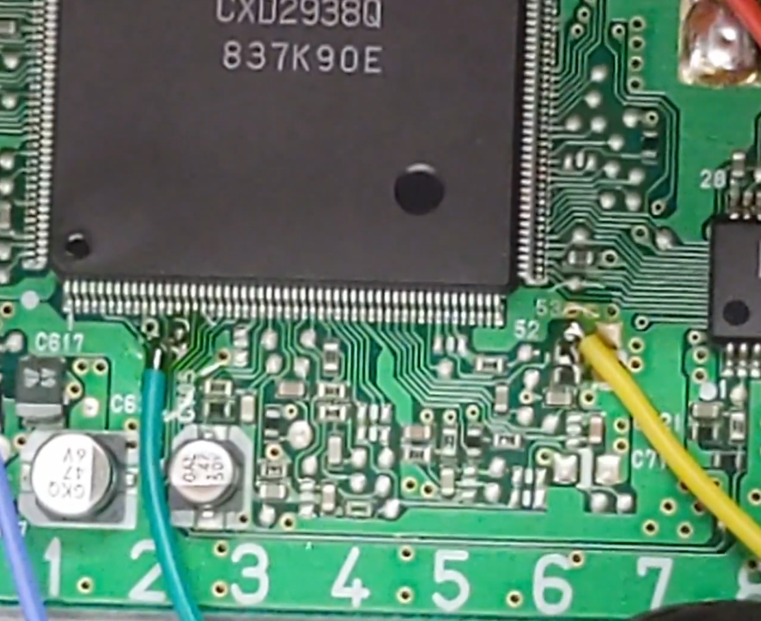
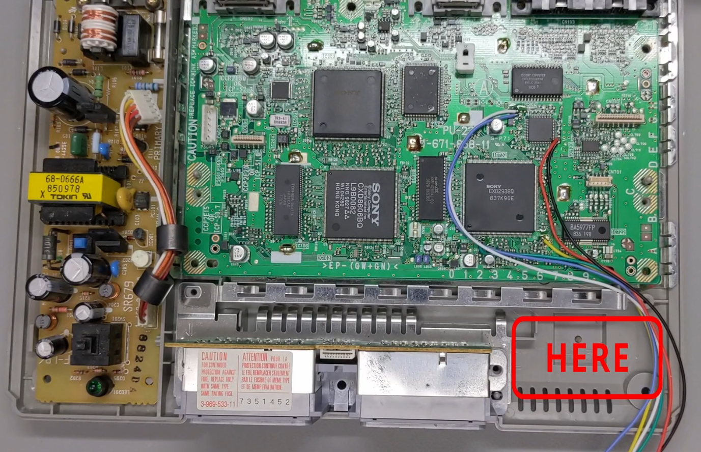
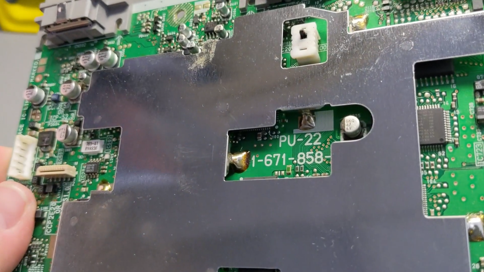
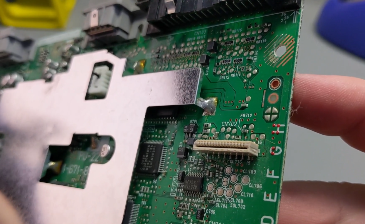
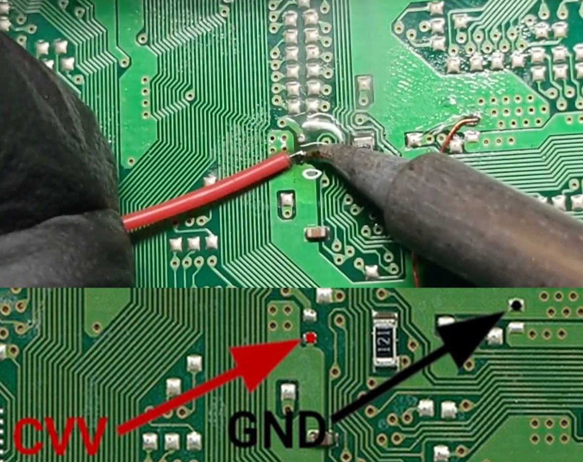
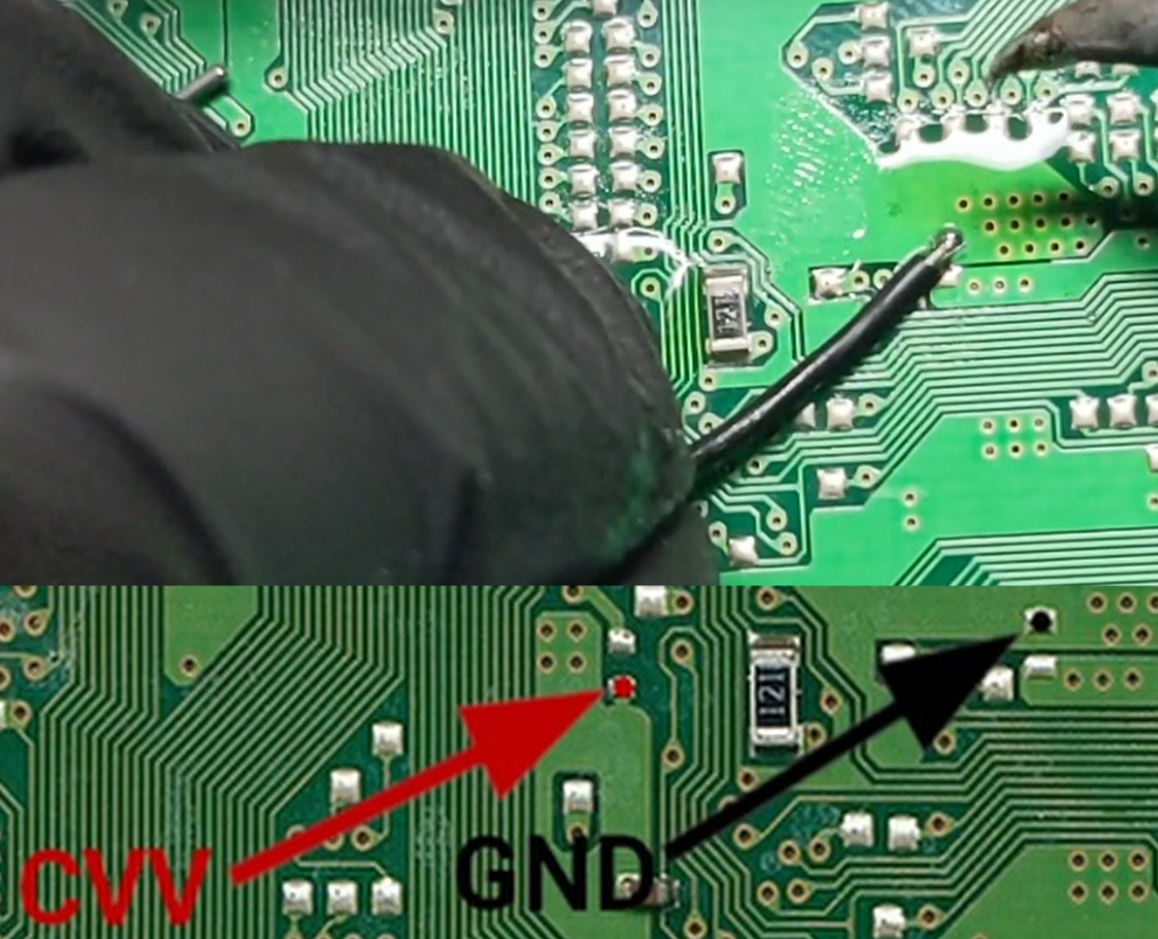
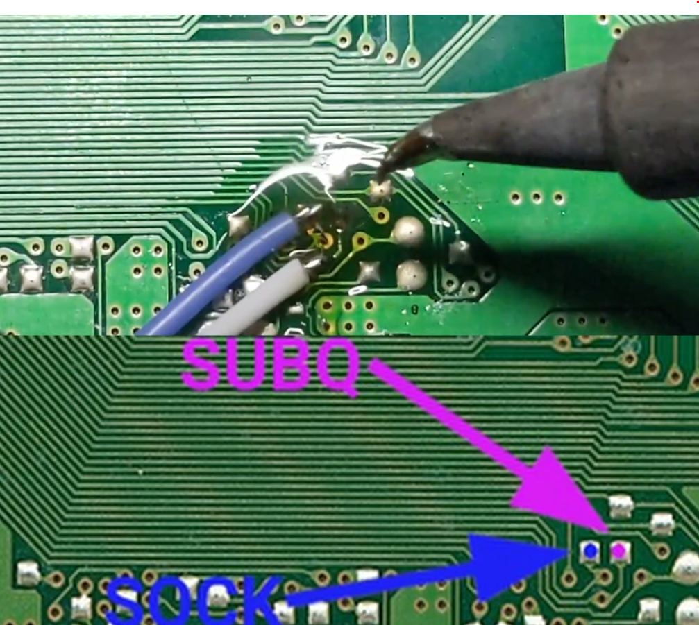
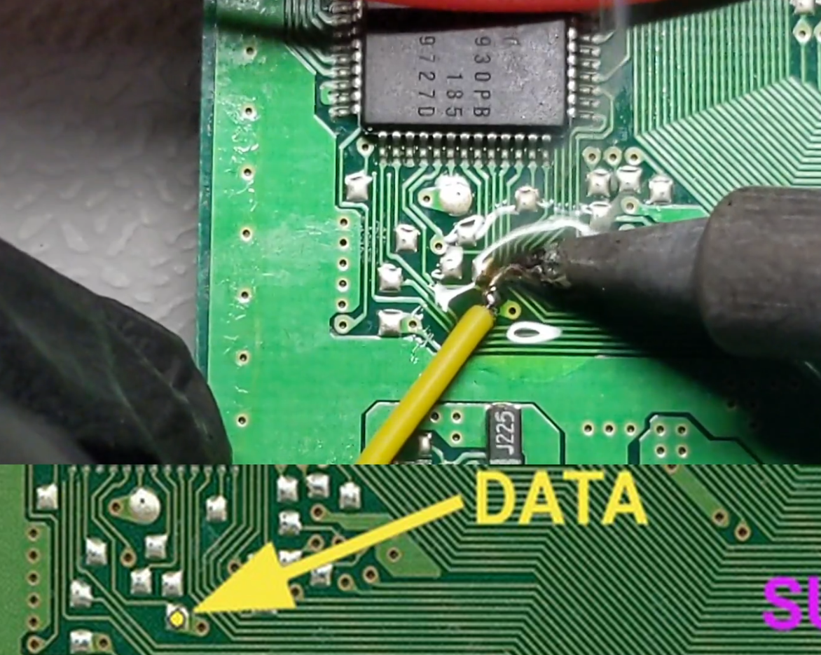
Let’s take a look at the PsNee wiring diagram for the PU-22 board from my SCPH-7501 PlayStation. There are 6 wires that need to be connected. I am starting off with the ground and voltage wires. These wires get connected to each end of the capacitor shown in the diagram. I’ll be using different color wires to match the colors shown in the PsNee installation guide. The grounding wire is the black wire and the voltage wire is red. The next two wires are the SUBQ and the SQCK signal wires. According to the documentation, These two connections are part of the bus that tells the PlayStation where the laser is positioned on the disk. I do not have any pink wire for the SUBQ connection, so I will use a white wire instead. The SQCK connection is the pad immediately below, shown here in blue. The 2 remaining connections are marked GATE and DATA. The gate wire gets connected to the pad below the big IC that is closer to the edge of the PCB. I am using a green wire. The DATA connection is this pad near the corner of the big IC that is beside the numbers 52 and 53. I am using a yellow wire for this one.
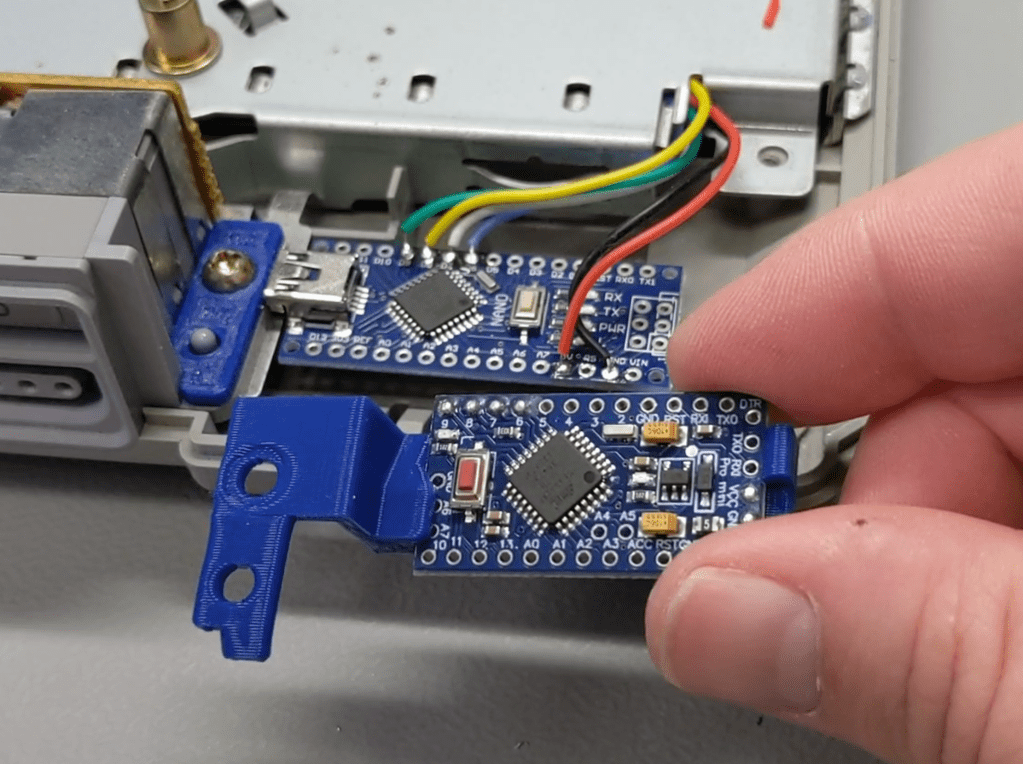
Now I need to make something clear. Generally, when you are installing a modchip, you want to keep the wires as short as possible. But I’m not going to do that here. I have been experimenting with this mod using different types and different lengths of wire and I’ve had success either way. So in this example I’m going to leave the wires a little longer to position the Arduino in the empty space at the front of the PlayStation.
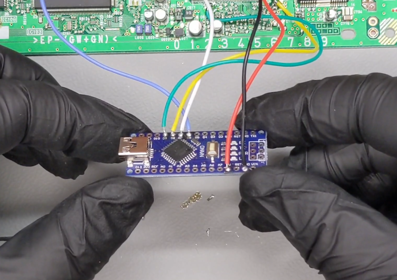
Now it’s time to connect the Arduino Nano. Having color coded wires makes this an easy job. The black wire gets connected to ground. The red wire gets connected to 5V. The green wire gets connected to pin 9. The yellow wire gets connected to pin 8. The white wire gets connected to pin 7 and the blue wire gets connected to pin 6. And that’s it, now that the modchip is connected the PlayStation can be reassembled.
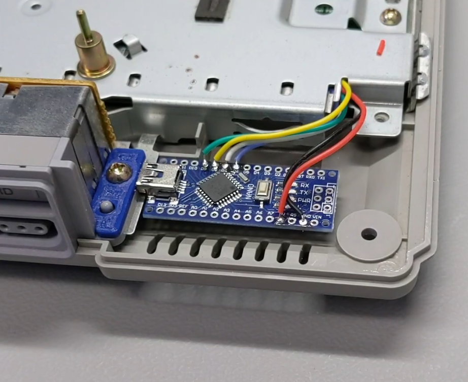
So, you actually don’t need to reinstall the metal shield. The PlayStation will work just fine without it, but I’m going to put it back on anyway. I just need to be careful with the wires when putting all this back in. I designed a little 3Dprinted bracket to hold the Arduino Nano in place. I also made one for the ProMini. You just install it under the screw on the right side of the controller ports. The STL file for these brackets is available for free on my Printables.com page.


So, have you taken a look at the install guide yet? There are a bunch of different versions of the PS1. Let’s take a quick look at another model so you can see some of the differences across these revisions.
This is my SCPH-5501 PlayStation that I have been using to test out some modchips. The PU-18 board does not have the same metal shield. This motherboard cover looks more like a flap of copper tape or something. But that actually doesn’t matter because on this model the connection points are all accessible on the back side of the board. Let’s take a look at the wiring diagram. Even though this board is different, the same 6 wires are required. Power, Ground, SQCK, SUBQ (Yes, I’m soldering to a VIA on this one because the pad lifted off the PCB as soon as I touched it with the iron.), DATA and GATE. On this one I’m going to run the wires through this hole in the PCB to keep them together. Hopefully, this will demonstrate how the installation process is pretty much the same, even on different models.
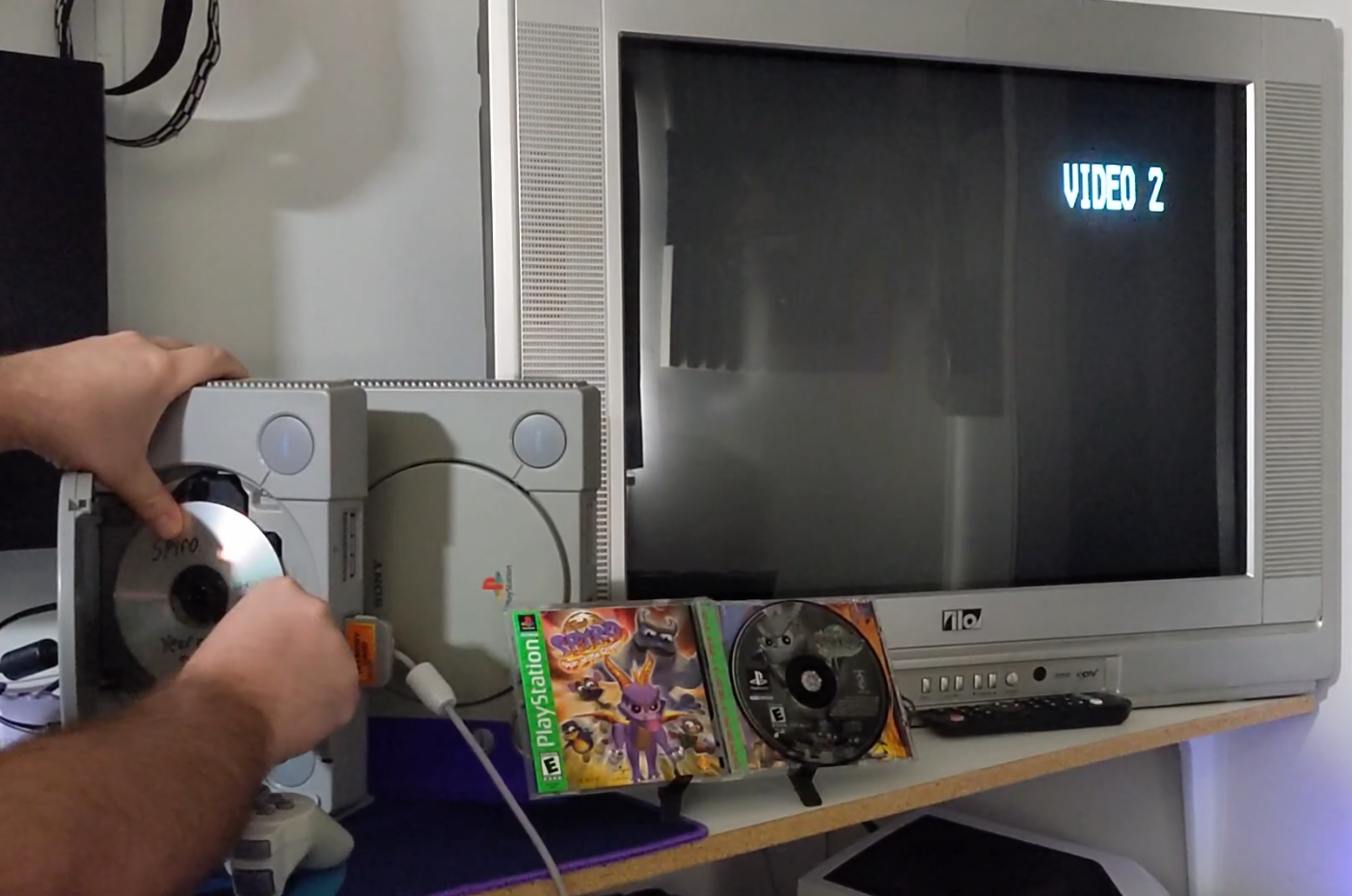
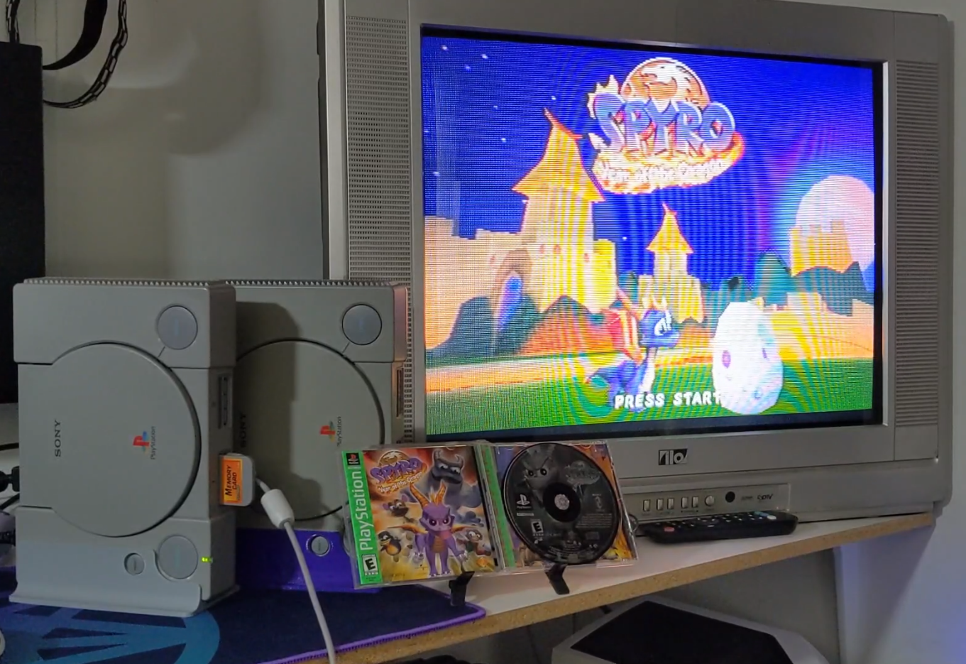
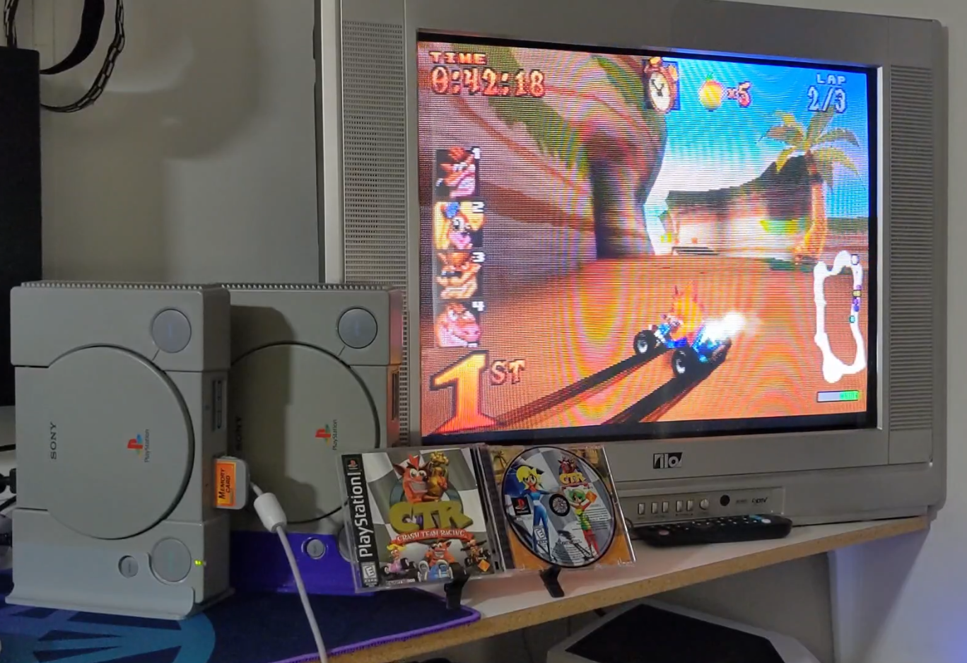
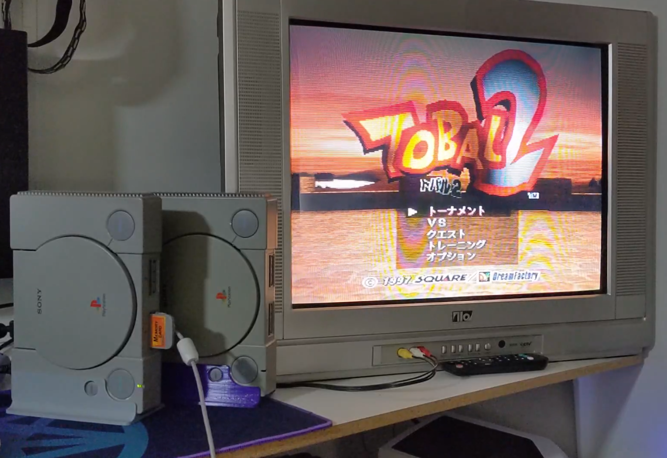
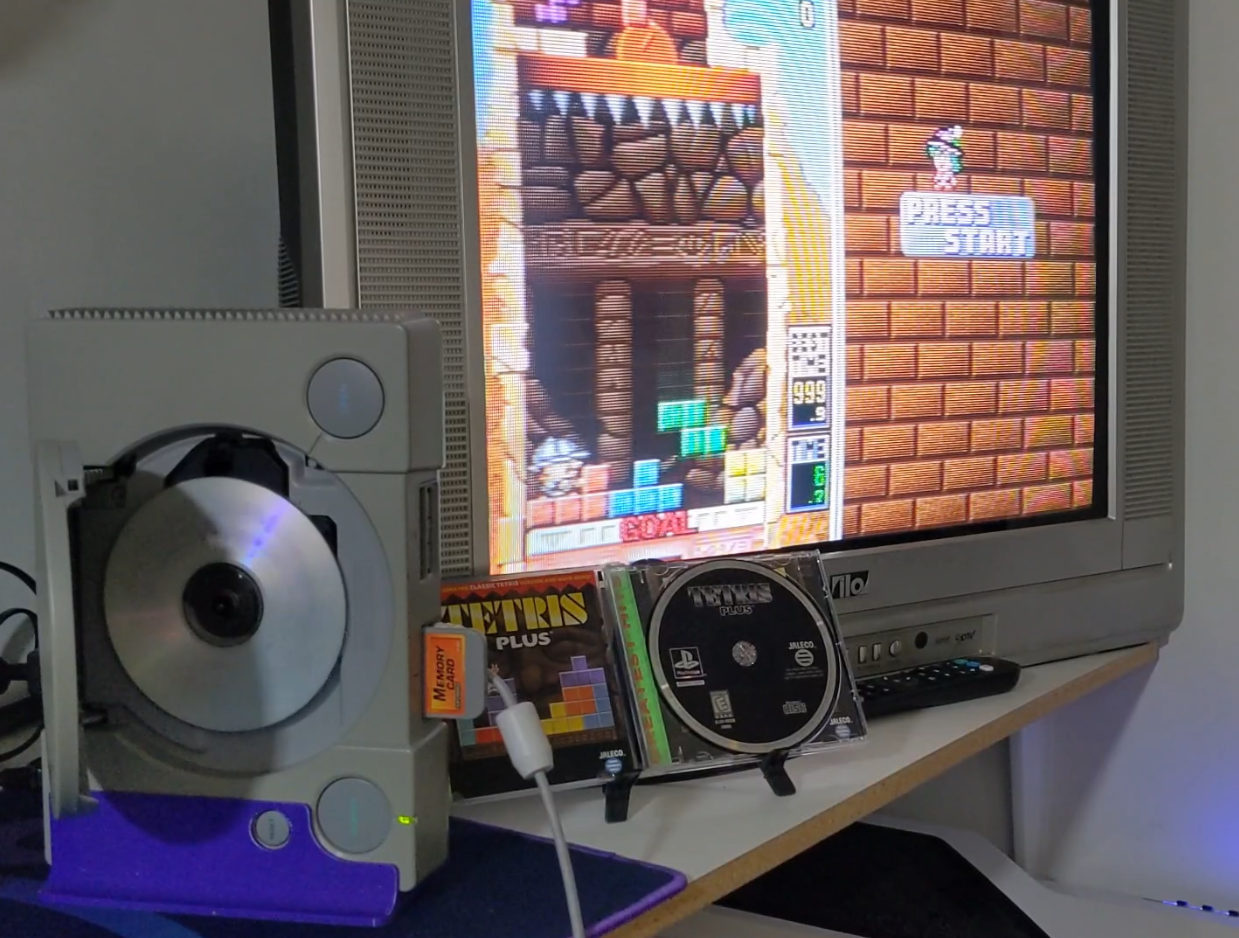
Its finally time to play some video games. The systems will now load burned game backup disks. I also tested out Tobal 2 since it was never released in the United States. Both systems appear to still be working pretty well even though the optical drives have been in use for many hours. Since the 5501 PlayStation has been used for testing I decided to leave the door detection switch disabled so it can run with the door open.
In summary, PsNee is a really cool project. Arduino boards are cheap and easy to acquire. The online documentation is clear and, compared to some modchips, It’s pretty simple to install. As I mentioned earlier, there are lots of ways you can enjoy PlayStation games. There are also some fantastic mods for the PlayStation hardware if you have a larger budget for something like an optical drive emulator.
If you like projects like this one, please check out my YouTube Channel. I really enjoy making videos despite all the criticism. Look for links to my other work below this article. Thank you for reading. Stay Mad.
-MML
https://www.youtube.com/madmodlabs
https://www.instagram.com/mad_mod_labs
https://www.tiktok.com/@madmodlabs

Leave a comment